Disclosure: Some of the links in this article may be affiliate links, which can provide compensation to me at no cost to you. if you decide to purchase. This site is for entertainment only.
When diagnosing a computer, there is always a feeling whether it is bad or not, since to reach the conclusion there is always a fear of making a mistake with the diagnosis, since an error can cost a lot of money and the fear of being wrong. in the diagnosis it is always present.
Here you can learn how to diagnose a computer if you are just starting out or already a little advanced in checking voltages.
Let’s get to the point where I show you what you need to diagnose.
1 A scanner
2 A voltmeter
3 Incandescent light tester not for led light
4 Electrical diagrams.
These four tools are essential to reach a good diagnosis.
And in case your battery is low in voltage, you need a power charger.
First, make sure the battery is in a good state of charging 12.5 volts to start with, or just plug it into the charger if it’s less than 12 volts while you test.
WHY USE THE SCANNER
1 A scanner is essential to diagnose a bad computer. With the scanner, you can read the codes and see if there is communication with the ECM.
2 A voltmeter is also essential to diagnose a bad computer. By checking the voltage at different points in the circuit, you can see if there is a problem with the power supply to the computer
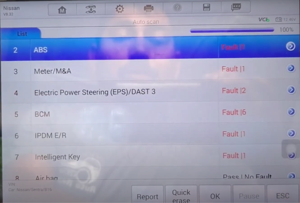
First, use the scanner, you can scan automatically if you have that option or simply scan the ECM to see if it has communication with the scanner,

if there is no communication with the ECM, scan all the other computers since that way you will know if it is a cable problem or it is just the ECM not communicating with the scanner.
This result will lead you to take the next step in your diagnosis.
HOW TO CHECK THE POWER SUPPLY TO THE COMPUTER.
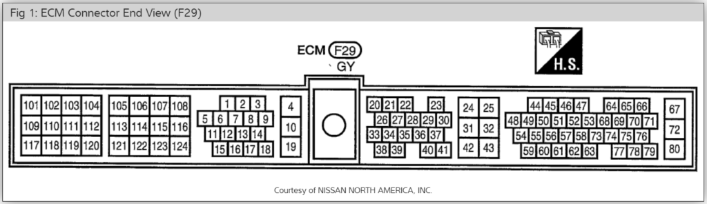
In order for the computer to communicate, it needs voltage and ground, the first thing to do is check the supply voltages to the ECM, here you need the electrical diagram to know which are the wires and locations that feed voltages to the ECM and which are ground.
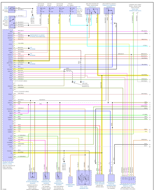
WHY USE THE ELECTRICAL DIAGRAM?
For example, in this Nissan, if you do not have information on the diagram, you will not know the location of the wires feed and colors.
Here you can use the voltmeter to find out how many voltages are feeding the ECM. You can do it simply with the switch on. But it will also be necessary to check it by cranking the engine.
No less than ten voltages are acceptable for cranking the motor.
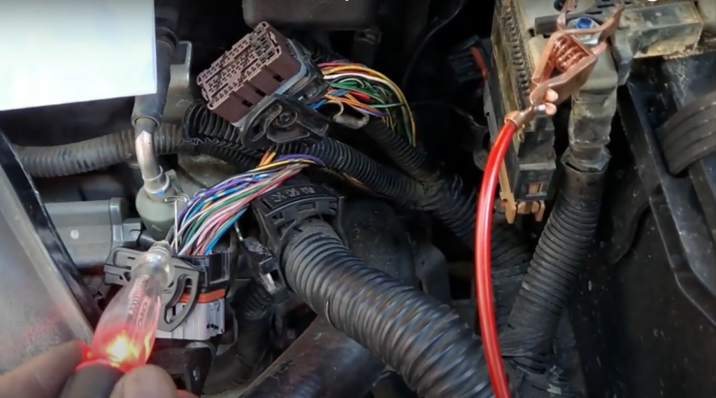
Or also use the light tester but with it, you will not see voltages
But it is very important since with the test light you will know if there is a wiring problem. Since using the test light you are putting a load on the wire circuit.
If you have 12 voltages on all feeds now you have to check the feed ground, with the voltmeter you have to read millivolts.
Less than 200 millivolts are considered normal, you also have to use the light tester, and cranking the engine should give a bright light
.
WHY USE AN INCANDESCENT LIGHT TESTER?
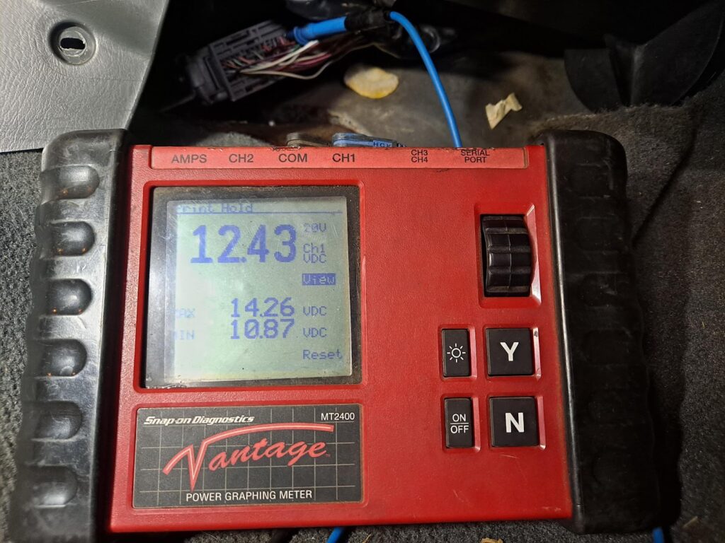
We have 12.43 voltage which is fine with the multimeter now if we put the test light on it let’s see if it really holds 12.43 voltage.
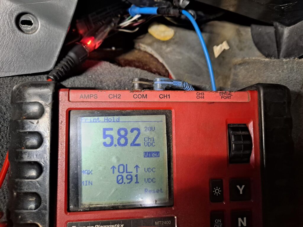
As you can see the 12.43 voltages when we put the test light on it we are putting a load on the system and now it really is only 5.82 voltages.
This is an example of a resistance problem somewhere in the circuit.
Now if you have good feed voltage and good ground feed it’s time to check the output voltages from the ECM. If the ECM has power supply voltages and ground it has to have output voltages.
CHECK THE OUTPUT VOLTAGES. FIVE VOLTS AND GROUND AT ECM.
Here you use the electrical diagram and find the five reference voltages that go to the sensors and also the ground. For example temperature sensor, MAF sensor, throttle sensor, etc.

Here you can find zero voltages or less than five voltages which indicates that there are problems with the ECM.
Sometimes you can have a sensor that is shorting to ground, to rule out that problem you have to disconnect the sensors and see if the five reference voltages return.
Finally, you can check the communication cables attached to the ECM you can find that it has about two to three voltages, you can compare it with the voltages of the other computers since they are the same voltage network.
If there are no voltages disconnect the ECM to see if the voltages return.
CONCLUSION
The scanner communicates with all other computers but not with the ECM.
The power supply voltage and ground are ok.
You have less than five reference voltages to the sensors and no ground.
The communication wires have the same voltages as the other computers.
With these tests, you can be sure that the ECM is bad,
BAD ECM SYMPTOMS
On some occasions, you may have symptoms, such as fans turning on by themselves. I have seen them a lot in Nissans when you put the switch on or noise from sensors that have a motor or things that activate themselves.
Other times you can have communication with the ECM and then no communication without you having moved connectors.
Pingback: HOW TO TEST ALTERNATOR – felivina